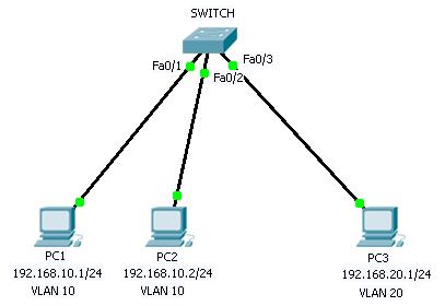
We have topology where there are 3 PCs, PC1 is connected to VLAN 10 through interface Fa0/1, PC2 to VLAN 10 through Fa0/2 and PC3 into VLAN 20 through interface Fa0/3.
CONFIGURATION :
- Create new VLAN
First, use the command "show vlan brief" in privileged mode to display a list of VLANs on the switch.
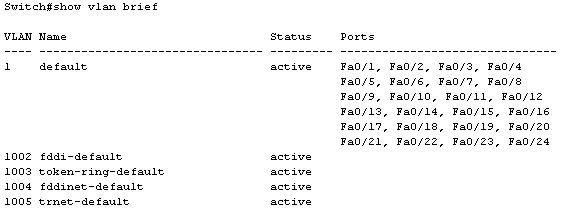
Based on the output above, it is default VLAN membership on the Cisco switch which is where all interfaces are assigned to VLAN 1. Now we will configure two new VLANs : VLAN 10 and VLAN 20.
To create a new VLAN database, use the command "vlan <vlan id 1-1005>" in global configuration mode.
Create VLAN 10.
Switch(config)#vlan 10
Name this VLAN10 with the command "name <VLAN_NAME>". For example VLAN 10 named VLAN 10.
Switch(config-vlan)#name VLAN10
Do the same for VLAN 20.
Switch(config)#vlan 20
Switch(config-vlan)#name VLAN20
Switch(config-vlan)#name VLAN20
Now we have two new VLANs, VLAN 10 and VLAN 20.
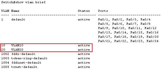
- Assign interfaces to respective VLAN
The next step is assign switch interface to respective VLAN. So assign interface fa0/1, fa0/2 to VLAN 10, and fa0/3 to VLAN 20 by using this command "switchport mode access" followed by "switchport access vlan [vlan id]" in interface configuration mode.
Assign interface fa0/1 and fa0/2 to VLAN 10.
Switch(config)#interface fa0/1
Switch(config-if)#switchport mode access
Switch(config-if)#switchport access vlan 10
Switch(config-if)#switchport mode access
Switch(config-if)#switchport access vlan 10
Switch(config)#interface fa0/2
Switch(config-if)#switchport mode access
Switch(config-if)#switchport access vlan 10
Do the same thing to assign interface fa0/3 to VLAN 20.
Switch(config)#interface fa0/3
Switch(config-if)#switchport mode access
Switch(config-if)#switchport access vlan 20
Verification :
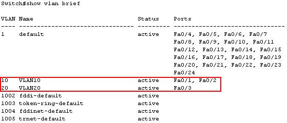
Now the interface fa0/1 and fa0/2 has been assigned to VLAN 10, and fa0/3 to VLAN 20.
Use the command "show vlan brief" to display VLAN database and their assigned interface.
Testing :
Now PC1 can't communicate with PC3 due to different VLANs.
PC1 (192.168.10.1) ping to PC3 (192.168.20.1)
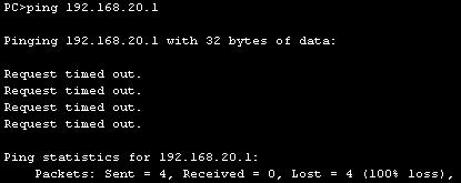
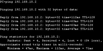
While PC1 still being able to communicate with PC2 because they both PCs are in the same VLAN.
PC1 (192.168.10.1) ping to PC2 (192.168.10.2).
Lab exercise :
- Configuration download
- Configuration solution download
- Troubleshoot download
- Troubleshoot solution download
Open the lab file with Packet Tracer.
No comments:
Post a Comment
Note: Only a member of this blog may post a comment.